555 Timer Schematic Diagram - Simple Dc To Dc Converter Using 555 Time Ic 6v To 35 Volts Boost Converter / Connect pin 1 of a 555 timer ic to the ground.
byAdmin-
0
555 Timer Schematic Diagram - Simple Dc To Dc Converter Using 555 Time Ic 6v To 35 Volts Boost Converter / Connect pin 1 of a 555 timer ic to the ground.. The 555 timer is a simple integrated circuit that can be used to make many different electronic circuits. There is also a 556 dual version of 555 timer which consists of two complete 555 timers in 14 dip and a 558 quadruple timer which is consisting of four 555 timer in one ic and is available as a 16 pin dip in the market. The breadboard schematic of the above circuit is shown below. The circuit diagram to operate the 555 ic in astable mode is shown be In this video we look at a simple 555 astable circuit.
We would like to show you a description here but the site won't allow us. We have seen in the last few tutorials that the 555 timer can be configured with externally connected components as multivibrators, oscillators and timers, with timing intervals ranging from a few microseconds to many hours. Its name is derived from three 5k ohm resistors ,connected in series used in it.the timer ic can produce required waveform accurately. We connect a 100μf capacitor to the positive voltage supply and then to pin 2. The schematic shows the connections, but doesn't really tell you how.
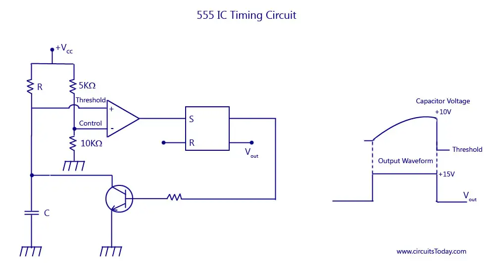
555 Timer Ic Block Diagram Working Pin Out Configuration Data Sheet from www.circuitstoday.com The next diagram shows the basic current consumption of 555 timer chips from different manufacturers. 555 timer ic working principle block diagram circuit schematics. Ground (gnd) it's the common ground point of the circuit. Referring to the timing diagram in figure 3, a low voltage pulse applied to the trigger input (pin 2) causes the output voltage at pin 3 to go from low to high. In this video we look at a simple 555 astable circuit. The breadboard schematic of the above circuit is shown below. The values of r1 and c1 determine how long the output will remain high. The 555 timer starts timing when switched on.
This integrated circuit can be used in a variety of ways from which the basic one is to produce accurate and stable delays in electronic circuits.additionally, it is available in 8 pin dip and 14 pin dip.
The 555 timer starts timing when switched on. 555 timers are very popular in electronics. This controlling can be done by selecting the appropriate values for the resistor r1,r2 and capacitor c1. As discussed in the above section, the ic is in its standard monostable mode. As the name indicates, only one state is stable and the other one is called unstable or quasi stable state. Resistive network consists of three equal resistors and acts as a voltage divider. The values of r1 and c1 determine how long the output will remain high. The circuit symbol for a 555 (and 556) is a box with the pins arranged to suit the circuit diagram: Pin diagram of 555 ic. It monitors the charging of the timing capacitor in astable and monostable circuits. Let us discuss in detail about this circuit. In the place of the push switch s1 / trigger switch you can also connect the output of any project to trigger the timer. The 555 timer delay before turn on circuit we will build is shown below.
Awesome 555 timer ic projects · 1. If a 10uf timing capacitor is used, calculate the value of the resistor required to produce a minimum output time delay of 500ms. The circuit symbol for a 555 (and 556) is a box with the pins arranged to suit the circuit diagram: Blinking led using 555 timer. These on off intervals can be adjusted by varying the 555 timer output and number of counter outputs.
555 Timer 8 Steps With Pictures Instructables from content.instructables.com The 555 timer starts timing when switched on. Basic 555 monostable multivibrator circuit. An external triggering is required for transition from stable to unstable state. This controlling can be done by selecting the appropriate values for the resistor r1,r2 and capacitor c1. The next diagram shows the basic current consumption of 555 timer chips from different manufacturers. A collection of 555 circuits using the 555 timer as an astable oscillator with different duty cycles. The breadboard schematic of the above circuit is shown below. With this information you will learn how how the 555 works and will have the experience to build some of the circuits below.
The 555 timer starts timing when switched on.
Working modes of 555 timer ic. The working modes of a 555 timer are astable, bistable, and monostable. After one minute of time duration, the led will automatically turn on. 555 ic timer block diagram 555 ic timer block diagram. This is a 555 one shot timer circuit. Additional • timing from microseconds through hours terminals are provided for triggering or resetting if • operates in both astable and monostable modes desired. You can find the pin structure of a 555 timer ic in the circuit diagram shown above. This integrated circuit can be used in a variety of ways from which the basic one is to produce accurate and stable delays in electronic circuits.additionally, it is available in 8 pin dip and 14 pin dip. This circuit uses very basic components like 555 timer and 4017 counter. Ground (gnd) it's the common ground point of the circuit. There is also a 556 dual version of 555 timer which consists of two complete 555 timers in 14 dip and a 558 quadruple timer which is consisting of four 555 timer in one ic and is available as a 16 pin dip in the market. Some devices will not function properly if the current to the threshold input is not restricted. In the place of the push switch s1 / trigger switch you can also connect the output of any project to trigger the timer.
The schematic shows the connections, but doesn't really tell you how. The circuit diagram to operate the 555 ic in astable mode is shown be The values of r1 and c1 determine how long the output will remain high. In the place of the push switch s1 / trigger switch you can also connect the output of any project to trigger the timer. Additional • timing from microseconds through hours terminals are provided for triggering or resetting if • operates in both astable and monostable modes desired.
Dark Activated Timer Using 555 Ic from circuits-diy.com 555 timer was first introduced by signetics corporation in 1971 as se555/ne555. This pin is either grounded or connected to the negative rail. These on off intervals can be adjusted by varying the 555 timer output and number of counter outputs. We would like to show you a description here but the site won't allow us. In this video we look at a simple 555 astable circuit. Figure 2 shows the basic 555 timer monostable circuit. If you are a beginner in electronics, you should learn the basics about a 555 timer ic, before you attempt to build 555 timer circuit or a full 555 timer project. Although the schematic looks correct, this basic circuit may actually have a few negative aspects.
In this mode, the circuit of the ic 555 timer produces the continuous pulses with exact frequency primarily based on the value of the two resistors and.
After one minute of time duration, the led will automatically turn on. 555 timer was first introduced by signetics corporation in 1971 as se555/ne555. 555 supply (pins 1 and 8). The schematic shows the connections, but doesn't really tell you how. Collect all the required components and place the 555 timer ic on the breadboard. It monitors the charging of the timing capacitor in astable and monostable circuits. 500ms is the same as saying 0.5s so by rearranging the formula above, we get the calculated value for the resistor, r as: You can find the pin structure of a 555 timer ic in the circuit diagram shown above. Adjustable on off timer(using 555 astable mode) in this circuit a timer with cyclic on off operations is designed. An external triggering is required for transition from stable to unstable state. The reset input current draw illustrates the need for a current limiting resistor as shown in some of the preceding circuits. In the place of the push switch s1 / trigger switch you can also connect the output of any project to trigger the timer. Its name is derived from three 5k ohm resistors ,connected in series used in it.the timer ic can produce required waveform accurately.
A monostable 555 timer is required to produce a time delay within a circuit 555 timer schematic. Basic 555 monostable multivibrator circuit.